A Nasal-Based Electrical System for Flightgear, v 1.1
By Gary "Buckaroo" Neely
This is a simple, extensible electrical system written using Nasal script and loosely modeled after the default Flightgear electrical system written in C. If you can install a ready-made nasal file and modify a little XML, you can rapidly implement a functional and extensible electrical system.
Overview
Components
Connectors
Example
Installation
Flightgear Integration
Advanced Connector Options
Troubleshooting
Additional Examples
Version History
Design Notes
Overview
The idea is to propagate voltages through a series of connected components. The system doesn't try to accurately model voltages, nor does it (yet) model amp usage or battery charging. There are many simplifications, but if you want a fast and easy way to model whether an electrical component is powered-up, it will do the job.
The basics: you define a list of components and a list of connectors that tie components together. Components are of 4 kinds: battery, alternator, external power, and output. The first three are called sources, while an output is anything that can receive power from another component. A connector takes one component as an input and conditionally propagates the input voltage to a second component, the output. A connector can include any number of switches which determine whether the inmput voltage is propagated to the output. That's all there is to it.
My system is released under GPL v2 and may be used or abused as you like. As far as I know, it works with any reasonably recent version of Flightgear. You don't need any nasal scripting knowledge, all you need to do is create and install a relatively simple XML configuration file, and I give several examples below.
If all this sounds interesting, read on to learn how to use it. Don't worry if this gets a little wordy, the system is actually pretty simple.
Components
Components are the electrical objects that will be linked together to form a circuit. For example, a simple circuit consisting of a battery and a lamp uses two components. Each compoment is made up of these possible elements:
name
type (must be one of: battery, alternator, external, output)
volts (required for suppliers)
property 1 ... property n (1 required)
source-property (required for alternator types)
source-min (required for alternator type)
The component's name is very important as it uniquely identifies the component. Make sure all component names are reasonable and unique.
Supplier components are batteries, alternators, and externals (ground service). Suppliers require a name, volts, and at least one Flightgear property acting as a terminal that will receive its output voltage, making it available for animations, etc. Suppliers normally will have a single terminal property. Volts is the supplier's ideal value. For batteries, ideal volts are simply copied to the output property. Externals do the same if the aircraft is on the ground and stopped, otherwise their output property receives 0 volts. Alternators deliver their ideal output if their source-property has a value greater than source-min. For example, the source might be "engines/engine[0]/rpm", and the minimum value might be 600. Below 600, the alternator delivers diminishing volts. These are very simple implementations, but the system is internally set up to make it easy to substitute your own supplier handlers.
Output components represent electrical devices that receive power or provide some function. Examples are lamps, instruments, mechanical devices, and buses. Outputs require only a name and one or more terminal properties. This type of compoment receives volts from another source (see connectors below) and this voltage value is copied to all terminal properties of the component. A typical output will have a single terminal property, but a bus might have several terminal properties to represent components that are unconditionally tied to the bus. This is a simple way to power non-switched systems. More on this later.
Note that I don't explicitly define a bus component. A bus is simply an output that is used as a voltage source for one or more dependent components. More on that later.
It's important to understand that the electrical system does not create any functionality for an output. Defining a 'cockpit-lamp' component doesn't create a lamp for your cockpit-- all it does is create a property that can be used to indicate whether a lamp is on or not. Many Flightgear instrumentation systems require a property having positive electrical power, and a component can be used for that purpose.
A meaningful electrical system will have at least one supplier and one output. The simplest system might have a battery to supply power and a light to receive power. To make it work, you need something to tie the two together.
Connectors
Connectors are the 'wires' that link components together. You can have one or more connectors consisting of the following possible elements:
input
output
switch 1 ... switch n (all optional)
scheme (optional)
factor (optional) name (optional)
Connectors allow one component (the output) to take on the voltage value of another component (the input). In the simple battery and lamp example, you'd use a connector to have the lamp receive the battery's volts. The connector can contain a switch which will determine the lamp's powered state.
A connector can have one or more switches, or none at all. Each switch is the name of a Flightgear property and must test as true (greater than 0) for the input voltage to propagate to the output. If a specified property does not exist, it will be ignored and test as true. Switches are processed in series, so multiple switches on a connector must all test true or the output will receive 0 volts. If no switches are specified, the input voltage will unconditionally propagate to the output. Note that a switch need not be a literal 'switch', but might be a circuit-breaker, a fuse, or a variable control.
Connectors are processed in order of definition, so connectors for suppliers to buses should be defined first, followed by bus to bus connections, and finally by bus to end-user outputs. In this way, voltage propagates from suppliers to buses and then to end-user outputs. Your system can be as simple as a single supplier tied unconditionally to a single output, or a multi-source system powering an AC bus, a DC bus, several sub-buses, and many end-user components, all through a series of switches.
Connectors have additional optional elements that provide more control over the value propagated by a connector. See Advanced Connector Options
Connectors may be named. This element may be omitted. Connectors are identified by their definition sequence in the XML configuration file, i.e., 0, 1, 2, etc. In order to provide more meaningful output in the system's error-reporting, connectors may be given a name. This may help you when diagnosing problems. Connector names are not otherwise used.
An Example
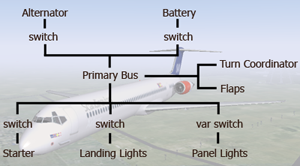
Let's assemble a working useful example that might be used for a light single-engine aircraft design. The design calls for an alternator, a battery, a primary bus powering several non-switched outputs and several switched outputs. In terms of the electrical system, this requires defines six components: two sources (alternator, battery) and four outputs (primary bus, starter, landing lights, panel lights). These are tied together using five switched connectors. Graphically, here's what the configuration looks like:
   Alternator          Battery
       |                  |
     switch             switch
       |                  |
       +------------------+
                |                  +-- Turn Coordinator
           Primary Bus ------------|
                |                  +-- Flaps
    +-----------+------------+
    |           |            |
  switch      switch       switch
    |           |            |
 Starter Landing Lights Panel Lights
Here is what our electrical system XML looks like: Configuration XML
We have the typical twin master switch configuration tying the alternator and battery sources to the primary bus. The switches must be on (their properties must be true or greater than 0) in order for the source to propagate voltage to the primary bus component. Of course the real situation is more complex than this, but here we're not interested in modeling battery charging or ground connections, we only care about whether something can normally deliver power to something else. In this case, either the alternator or the battery can provide power to the primary bus if their respective switches are on. In the case of the alternator, it will provide full output only if the engine's RPM exceeds 600.
The Primary Bus is just a standard output component with a slight twist, which we'll come back to in a moment. The starter, landing lights, and panel lights are each defined by a separate component and linked to the primary bus component via a connector. These connectors all use a switch property, and the switches must of course be on for power to propagate from the primary bus to the dependent component. If the primary bus is not powered, none of these components will recieve power regardless of their switch settings.
Remember that connector sequencing in the configuration file is important. The two connectors for the alternator and battery are placed ahead of the three for the starter and lights. If a starter connector was placed before the the source connectors, the starter might get a false voltage reading because the primary bus voltage would be updated /after/ the starter voltage. This requirement applies only to connectors. Components can be defined in any order.
Most output components need a single terminal property, but you can define more than one to receive the propagated voltage. Here, the primary bus component has three output properties labled 'bus-dc', 'turn-coordinator', and 'flaps'. The starter, landing lights and panel lights are all tied to the 'bus-dc' property via connectors because they are switched components. But the turn coordinator and flaps are not switched, they are always powered if the primary bus is powered, so we can simplify the system by simply giving them properties associated with the primary bus rather than defining components and connectors for them. This simplifies your XML configuration file, and for complex electrical systems it's more efficient to provide outputs this way rather than to define a component and a connector. Note that these non-switched systems could all refer to the 'bus-dc' property for electrical power status, but the system gives gives you the option to define their own terminal properties on the bus.
Installation
Setting up this electrical system requires you to do two things: define an XML configuration file specifying your components and connectors, and install the nasal controller file.
First, copy and save the Electrical.nas file to wherever you keep your aircraft nasal files, and create a reference to it in your aircraft's primary -set.xml file. For example:
<nasal>
  <MyPlane>
  <file>Aircraft/MyPlane/Nasal/Electrical.nas</file>
  </MyPlane>
</nasal>
You will not need to modify the nasal script unless you want to change default locations, update frequency, or customize anything.
Next, create an XML file to define your electrical system. Feel free to use any of my examples as starting templates.
In your electrical configuration file, make sure you have included the <path></path> element as shown in my examples. This disables the default Flightgear electrical system and is important to proper installation of the electrical system. If you don't do this, the default Flightgear electrical system will run and conflict with this system, causing weird problems.
Save your configuration file as something like 'electrical_config.xml' somewhere logical in your aircraft's directory. I place my file in a 'Systems/' directory. Then in your aircraft -set.xml file you would include the following in the <sim> section:
<systems include="Systems/electrical_config.xml">
</systems>
Integration with Flightgear Systems
It's important to understand that the real product of this system is the electrical component's terminal output property. These are the properties that are used by the rest of your aircraft's configuration or animations. For example, if you create a component:
  <component>
    <kind type="string">output</kind>
    <name type="string">Landing Light</name>
    <prop type="string">/systems/electrical/outputs/landing-light</prop>
  </component>
It's the property "/systems/electrical/outputs/landing-light" that you likely want to use in your animations to test whether a light is on or off, not the value of the light's cockpit switch. You would use the light switch property in the light component's connector, but not in the animations.
Some Flightgear instruments and systems need electrical power, though these requirements are not well documented. Instrumentation may require an electrical ouput of the same name under /systems/electrical/outputs. For example, the standard turn coordinator system requires a positive value on /systems/electrical/outputs/turn-coordinator. If any instrumentation or system fails to operate as expected, open a property tree browser in Flightgear and check to see that you have an output with positive volts for that system. An easy way to address this is to add the system directly to a primary bus, like the turn coordinator in my example. For consistency with other Flightgear systems, I recommend following this standard and placing all your component output properties under /systems/electrical/outputs.
Advanced Connector Options
The primary function of a connector is to propagate the voltage value of the input component onto the output component if all switches test true. But you can modify the value received by the output by using the <scheme> and <factor> optional elements.
The <scheme> element allows the connector to propagate switch settings or values other than the basic input voltage. To use a scheme option, include one of the following optional elements:
  <scheme>volts</scheme>
  <scheme>switch</scheme>
  <scheme>switch-volts</scheme>
  <scheme>scalar</scheme>
The value placed on outputs is affected by your scheme selection:
  volts         propagates input volts (default case)
  switch        propagates the value of the last switch
  switch-volts  propagates volts * the value of the last switch
  scalar        propagates a real number
Volts is the default and most common case and need not be specified if simple voltage propagation is desired. If a switch-based scheme is used, only the value of the last switch defined on the connector is considered. If the scalar scheme is specified, one of two additional elements is required:
  <scalar-value><value></scalar-value>
  <scalar-prop><scalar property></scalar-prop>
Examples:
  <scalar-value>14.4</scalar-value>
  <scalar-prop>/sim/myplane/test</scalar-prop>
The first propagates a simple scalar value (this must be a real number). The second propagates the value found in the specified property (this must also be a real number). If the scalar scheme was selected but no valid value or property was specified, the connector will propagate a value of 1.
A connector may also specify an optional multiplier to the output value:
  <factor><value></factor>
  <factor-prop><scalar property></factor-prop>
If no valid factor is specified, 1 is assumed. The factor is applied to the output value after all other scheme calculations. For example, if you used the scheme 'switch-volts' where the input volts is 14, the switch value is 0.5 and you also specified a factor of 4, the output component would receive the value 28. You can have either factor or factor-prop but not both.
In all cases a connector's output will always receive a value of 0 if any switch tests false.
The switch scheme is particularly useful. This option propagates a switch setting rather than a voltage. This is handy for things like variable panel lights, allowing an animation to use a normalized switch value (0-1) rather than a voltage output.
You can do some neat tricks with these options. For example, <scheme> and <factor> elements can be combined to make a connector function like a transformer or even as a relay if the output component is itself a switch property.
Troubleshooting
When the electrical system is properly installed, you should see a notice in the command window saying "Initializing electrical system..." shortly after starting Flightgear. If you don't see this when your aircraft begins to load, the system's nasal file is probably not installed correctly. Check the installation procedure above and make sure you are referencing the right file in the
Once the electrical system is installed and your configuration file set up, the system will try to detect and inform you of any configuration problems it finds when your aircraft is loaded. When starting Flightgear, watch the command window. Immediately after the "Initializing electrical system..." message, the system will will inform you of any basic problems. You can avoid most errors if you make certain that:
component names are present and unique
components and connections have the required elements
connections don't try to output to a source
connections don't try to output to the input
connections don't refer to a missing component
connector schemes are valid and have all necessary subordinate elements
The electrical system will create and set all specified properties if they don't already exist, but it's good practice to pre-define your properties, specifying their type and default values as usual. It might save you from weird problems.
Additional Examples
A working example from my Edgley Optica model: Optica Configuration